Business Continuity

But even a momentary blip can cause big problems. Not every small enterprise or workgroup can quickly find the budget it takes for a soup-to-nuts business continuity solution. In some situations, though, integration of a point solution can keep a network up during power disruptions without causing a major disruption to an IT budget.
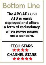
One such option is the AP7750 Automatic Transfer Switch (ATS) from American Power Conversion Corp., the West Kingston, R.I.-based infrastructure company, a unit of Schneider Electric. The AP7750, list priced at $559, can well fit the bill in many cases.
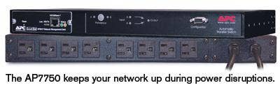
The AP7750 is a manageable, networked, rack ATS. Among many available variations, this model is a 100/120V device with two NEMA 5-15P input cables and eight NEMA 5-15R output receptacles.
After easily installing the 1U case into a rack in the CRN Test Center lab, reviewers connected the two 8-foot power cords to our power outlets. We also ran an Ethernet cable from our switch to the RJ-45 outlet on the front of the AP7750.
Following the directions in the Quick-Start guide made configuring the AP7750 for network accessibility simple. Defining the TCP/IP settings of the internal Management Card can be done by using the Configuration Wizard on the included CD, connecting to a BOOTP or DHCP server, attaching a local computer to the serial port or remotely accessing the device from a computer on the same subnet. We chose the latter option and had no problem connecting to the ATS and configuring it. The step-by-step instructions spell out every command that needs to be typed, and very little networking knowledge is necessary.
The front of the AP7750 is simplistic and is mostly filled with status LEDs, along with the RJ-45 connection, a preference button and the serial configuration port. The preference button allows the user to select the preferred source to supply power when both are available.
The LEDs allow the user to see the status of the ATS at a glance. There are source A and B lights that indicate when the RMS input voltage and frequency are within the tolerance range. When everything is operating normally (full source redundancy), both of these LEDs are illuminated. Next to each source LED is a connector LED in the shape of an arrow that shows which source is being used for output. Finally, there is an output indicator that shows voltage is available at the output sockets. The combination of source LEDs, connector LEDs and output LEDs presents a graphical view of the power flow through the ATS.
After configuring for the network, the browser-based management console allows for complete administration of the ATS. The upper right corner displays a graphical representation of the status LEDs and the status page shows the specifications of the source voltage as well as the state of the ATS' settings. The console also allows for easy configuration of the settings that govern the rules for when the device will transfer sources.
Other pages include an event log and network configuration, where the user can configure a variety of connection methods and protocols and e-mail recipients for event notifications. Lastly, the System page has sections for setting preferences, as well as user management to give multiple users a choice of access rights.
During testing, the ATS functioned exactly as expected. When power outages were simulated on the primary source, the switch seamlessly transferred power to the secondary and the logs documented everything.
In June, APC was named a 2008 CRN Channel Champion for the 15th consecutive year and recently launched redesigned partner programs. With four levels, the newly enhanced programs allow channel partners pricing and promotional benefits, plus support and access to APC's network of solution engineers.